When you click on links to various merchants on this site and make a purchase, this can result in this site earning a commission. Affiliate programs and affiliations include, but are not limited to, the eBay Partner Network.
I learned a long time ago (from Wagner or Gage) that the benefits of a smooth exhaust port is to prevent carbon build up; this could be ideas from the 90's so not trying to imply I'm an expert here. Also I was taught to consider there is zero air velocity on the surface therefore the surface finish has a lower significance to overall airflow: https://en.wikipedia.org/wiki/Boundary_layer_thickness
Another thing that comes to mind is the dimple port jobs, the polar opposite of a polished finish. Let's say you don't gain or lose anything with the dimple port job, that would still say a lot, like for sure the surface finish has little to do with flow. There isn't a whole lot of hard evidence, mostly speculation like this here.
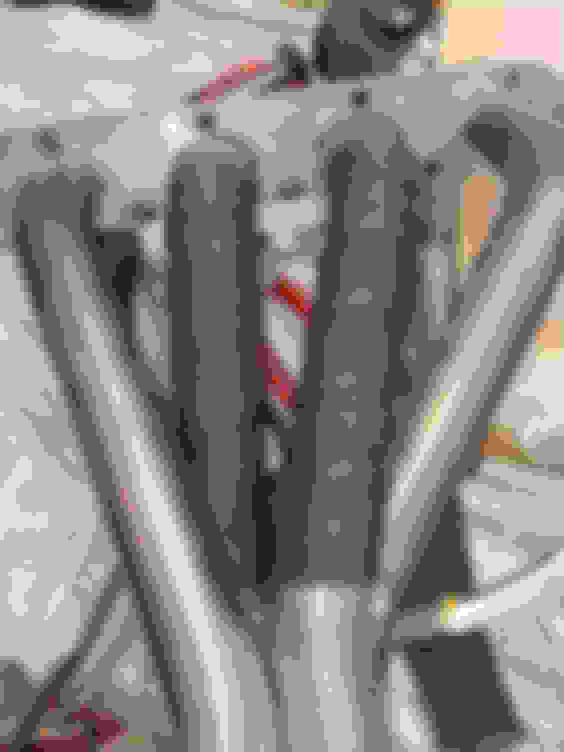
Not really even talking about the suface finish, did you look at the pics? The exhaust port volume changes drastically where its machined. I would imagine that ledge could cause some turbulance and hurt the flow, but like you said its just speculation.
Not really even talking about the suface finish, did you look at the pics? The exhaust port volume changes drastically where its machined. I would imagine that ledge could cause some turbulance and hurt the flow, but like you said its just speculation.
Not really even talking about the suface finish, did you look at the pics? The exhaust port volume changes drastically where its machined. I would imagine that ledge could cause some turbulance and hurt the flow, but like you said its just speculation.
Originally Posted by ECaulk
Time to do some CFD and see the effect
It's not as drastic as the photo makes it appear. The transition on the bottom of the ports is really pretty straight across. The cut away of the middle divider makes it look more drastic than it actually is. The top transition is more abrupt than the bottom but if you look close you can see it transitions from flush on the outer top part of the ports to only about a 1/8" offset on the inside portion of the ports near the divider. Also the photo almost makes the transition look square but it is actually rounded with probably about a 1/4" to 3/8" radius. Hopefully it won't have a significant impact on performance. If the transition does create drag in that location maybe it will just fill with carbon deposits and smooth itself out lol.
Not really even talking about the suface finish, did you look at the pics? The exhaust port volume changes drastically where its machined. I would imagine that ledge could cause some turbulance and hurt the flow, but like you said its just speculation.
Hi, this is Steelmesh back to reality from planet *******. I agree steps and aggressive transitions are known to negatively impact flow.
Things are slowly progressing though it doesn't seem like I'm getting very far I'm spending a good amount of time figuring things out like the hose routing for the intercooler system and how I'm going to do the intake. Below is how it currently sits. Hopefully I am to the point I can drop the car back onto the front cradle assembly by this weekend.
Mad a little more progress. Pretty much have Found a 1/4 JIC Female to 1/8 NPT Female swivel fitting on Amazon to adapt AEM fuel pressure sensor to L61 fuel rail after removing Schrader valve. PN: Eaton Aeroquip 2242-2-4S Oil pressure sensor location Found a 12mmX1.75 Male to 1/8 NPT Female adapter on SummitRacing to adapt oil pressure sensor. PN: ATM-2278 Water/Methanol injection lines and IC hoses. You may barely be able to make out that the second pump is installed down near the subframe with a hose coming out towards the radiator that will connect to stock LSJ h/e. Pump PN: DCW-DC-9040
the front cradle assembly ready to go back into the car. Currently waiting on fasteners for the exhaust manifold. In the meantime I plan on wrapping my header. Luckily I already had the larger bolts for the intake manifold because they are provided with phenolic spacer from ZZP. Have the IC hose routing all figured out and progressed as far as I can with the cradle assembly separate. Have fuel pressure sensor, oil pressure mounted and already ran wires from oil sensor since it is mounted under the IM. forgot to connect tube for MAP sensor so I will have to pop the fuel rail back off to do that. One thing I noticed was the injector isolators seem to fig much tighter in this LSJ head than they ever did in my L61 head. Water/methanol injection lines are ran. I'll just need to connect them to the pump. Hopefully drop the car back onto the cradle and be wiring this b this weekend.
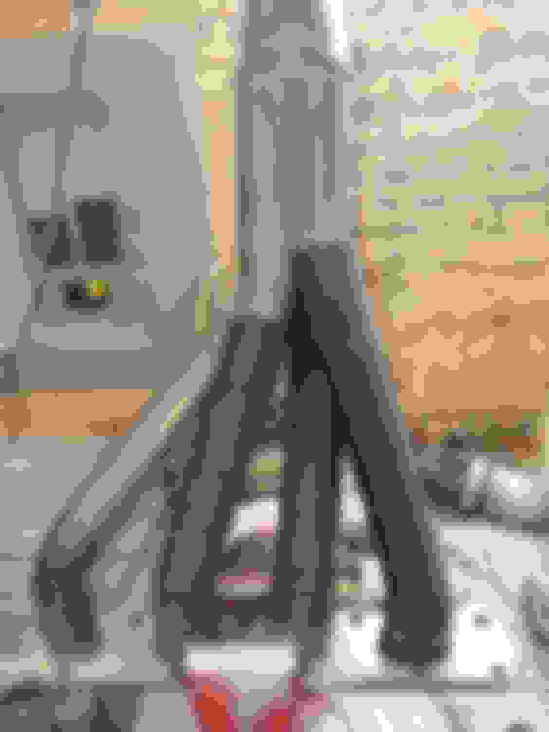
Ended up getting my headers wrapped before participating in cruise night. Was actually pretty easy. Got the wrap wet, folded the ends at the start a little to keep it from fraying and did the same at the termination then secured with some stainless zip strips. I've seen some people suggest stainless steel safety wire which I have on order but not here yet. I may end up using that and cutting these zip strips off. The 50' roll was pretty damn cheap on
Man your car is gonna be screaming down the roads when it's done. I think it's plausible, but ever thought about ceramic coating the TVS? Should help with thermals.
Man your car is gonna be screaming down the roads when it's done. I think it's plausible, but ever thought about ceramic coating the TVS? Should help with thermals.
Lol thanks but I just hope I can get the damn thing running right for once. No I hadn't really thought about the suprcharger as I think it generates most of it's own heat. When I autocross or anything I do spray the supercharger with a water mist between runs.
I bought about 5 different crimpers on the cheaper end of the spectrum and out of all of them I have found these to work the best for small terminals IWISS PN: IWS-1424B
Decided it would be easier to run most the wires with the front cradle outside of the car. I'm labeling each wire as I go so I can get it to the correct pin on the MIL connector on the firewall. The wires I am holding in this picture are actually the stock injector wires. I ended up having enough length cut out of the stock harness that I didn't have to rebuilt the fuel rail connector and run new wires. Unfortunately the throttle body wires are going to be just barely too short.
First step in rebuilding stock connector is to disassemble and remove old terminals. It's fairly straightforward and they make tools like he one in the picture that aids in popping out the terminals. I had to remove all the rubber seals from these wires because I didn't think about buying new though that would probably be easier. Freshly rebuilt TB connector before installing inner and outer keepers New TB connector installed
These are the connectors I like to use when splicing multiple wires together. They are waterproof crimp and solder. You have to carefully heat the whole assembly to melt the solder without melting the shrink material. Here you can see the connector crimped but not yet heated Finished product after heating to melt solder.
Cam/Crank sensor. It probably isn't necessary but I used a shielded wire to connect to ECS. I label each wire with white tape and sharpie. Each label has call-out for component and pin identification for MIL-spec plug. If I did everything correctly I should just be able to cut, strip, crimp and insert pin without any additional references. I ran and labeled one wire at a time to avoid mixing anything up. Wire harness finished without loom installed. I have excess wire going to ECT sensor because I haven't received the correct connector yet which is a freakin $35 connector which is BS. To get by in the meantime I rigged up some terminals protected by shrink tub. Finished harness Back side
looks good man. I know that has to feel satisfying cause wiring isn't fun
Thanks. I'm glad I decided to run the wiring with the cradle assembly outside of the car. Though yesterday I did finally get the engine back in the car. Thanks to Kolt I am able to utilize the stock fuse box to run fuse/relay for the cooling fan and the main EFI relay which powers the coils, injectors, widband sensor, and cam/crank hall effect sensor. Here you can see power wires and lowside relay trigger for EFI relay which is the old "Fan 1" relay. The two cooling fans are wired in parallel so there will be no high and low setting just on or off. Here you can see the lowside fan relay trigger being inserted. The two fans will both run off of the "Fan 2 relay" Hopefully get to installing all these wires into the MIL connector that interfaces at firewall tonight, firing up the AEM to sync timing and diagnose any wiring issues.

 06-11-2019, 11:35 AM
 Moderator