F35 - Project 6k sidestep
#1
F35 - Project 6k sidestep
Not that I am going to be ever sidestepping at 6k, it's simply the only suitable title for this thread. I want to have the confidence that the case won't break on boosted launches with slicks. I've already broken one trans drag racing on the streets of Mexico with only DRs. The broken 4.05 trans had less than 5k miles on it too lol. Thats what happens when you nearly dead hook on a boosted launch more than a few times.  I think the only thing I have to be worried about now is axles. I would much rather be replacing axles than trannies any day.
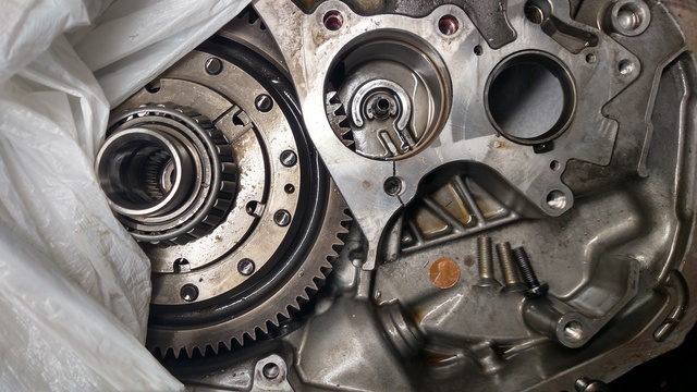
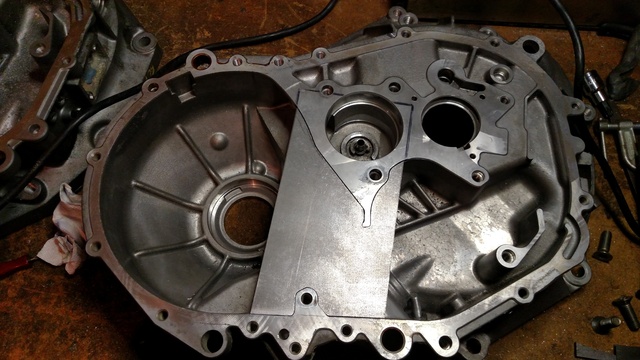
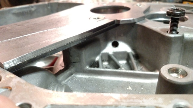
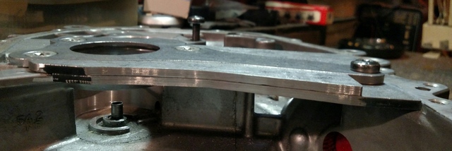
This picture shows an unfathomable amount of time for perfect fitment and the it's still being finalized. Reproduction of this brace milled from a chunk of aluminum is the ultimate goal and maybe have a few extra made .
.
This is a redesign of my first pinion brace which was being used in my 4.45 and was also an excellent upgrade with far less work involved and trans never split with all the launches on DRs it's seen. But this new brace is beast.


This picture shows an unfathomable amount of time for perfect fitment and the it's still being finalized. Reproduction of this brace milled from a chunk of aluminum is the ultimate goal and maybe have a few extra made
This is a redesign of my first pinion brace which was being used in my 4.45 and was also an excellent upgrade with far less work involved and trans never split with all the launches on DRs it's seen. But this new brace is beast.

#3
#8
Thank you for the support guys
That is the Idea actually. Taking the brace to a place locally to see what they can do as far as mapping the piece within my spec. If they can't, there is another option to achieve the desired tolerances but at more cost I think. As far as selling them, I cannot speak of that as I am not a approved vendor yet. As far as fitting them, I designed it to bolt in very easy but every brace will need minor custom fitment to each bellhousing.
Yessir.
Yessir.
#13
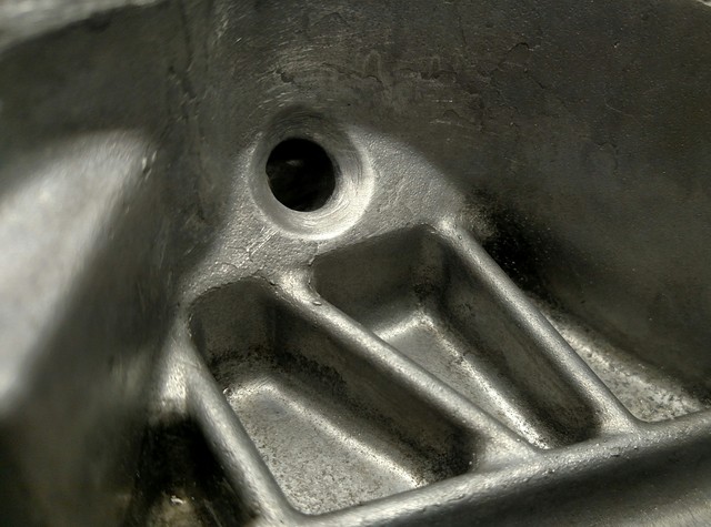
I am surprised nobody has claimed this brace will impede oil flow. Well, it does but not enough to be an issue. It impedes the flow 3/16" to be exact. The area underneath the brace is open to allow the differential to throw oil at the shift assembly and drains some of the fluid to a drain hole on pinion housing which you can see in pics above. That drain hole feeds the oil directly into output shaft. The output shaft is hollow and has designated oiling holes for the 1-2 syncronizer gears, hub, slider, and bushing assembly. There is a few ways to improve the flow to output shaft. The edges of the brace will be chamfered to allow fluid to travel over/under it much easier, and you could simply add a little bit more fluid than you normally would. One thing I like to do regardless what brace is in there is to countersink that drain hole just a little bit as shown below.
#16
#17
#19
Update.
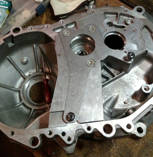
I had the pieces tig welded together and the heat from the welding warped the entire piece. We took as many precautions as possible to prevent this but it still warped a just a hair. Unacceptable, so I made another.
The goal was to finish the piece and have it scanned so dimensions were noted and on file. This way I could install the prototype in my trans and finish the build as I'm working with a deadline that is fast approaching. The first piece was designed to simply bolt in with minor milling but, I scrapped that idea and decided to go with a fitment that requires more milling to the bellhousing on diff side of pinion loop as I feel it will keep the pinion loop from trying to force itself under the brace. Some other fitment changes we made as well, for the better.
The new piece is now tack welded together so I should have some answers this week as far as reproduction possibilities.
#21
Will do James. Took the brace to couple different machine shops today and looks like I will have to shell out some decent cash for a cmm scan drawing that I will own. More updates to follow.
#23
I can not wait to work with the first run. 6061 will b a breeze to fit compared to steel. Next step is to make a jig to aid in custom fitment. I plan on having 5 or 10 braces manufactured and will be available if it passes the 4-6k boosted launch tests... On slicks

Fwiw, new bellhousings are still available for 550$
#24
Joined: 05-15-11
Posts: 27,413
Likes: 584
From: Livonia, MI
Ah i can see why youd want to be doing it locally then. I can find out exactly what kind of scanner it is on monday, the school is closed for the holiday right now.
If youre wanting to have the piece welded i would be careful using 6061. Make absolutely sure that it is annealed and not 6061-T6 or it will crack, guaranteed.
If youre wanting to have the piece welded i would be careful using 6061. Make absolutely sure that it is annealed and not 6061-T6 or it will crack, guaranteed.


 Moderator